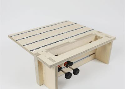
Vertical Workstation
By Shaper|BY-NC-SA 4.0 License|Created October 24th, 2017


5 hr
Advanced
248

Additional materials
This project requires some additional materials. We have provided multiple options for each of these items. Choose the option that best fits how you plan to use your workstation.
Track/Clamp Option 1 - Rockler T-Track + Clamps: These swivel clamps are the more flexible option and can accommodate a wide variety of material sizes and thicknesses.
Track/Clamp Option 2 - Peach Tree T-Track + Clamps:These clamps, are not as versatile as the Rockler clamps (these don’t swivel and have a smaller maximum material thickness). They do, however, provide better hold down force.
Alignment Pin Option 1 - Delrin (Acetal) Rod: This is the recommended material to use for the alignment pins. It’s cross section is much more predictable than wood dowel, making it more reliable as an alignment feature.
Alignment Pin Option 2 - Maple (or other hardwood) Dowel: Maple (or other hardwood) Dowel: If you plan to order material for these pins, get the Delrin. This is option provided as reference in case you already have ½” dowel you want to use.
Prepare your material
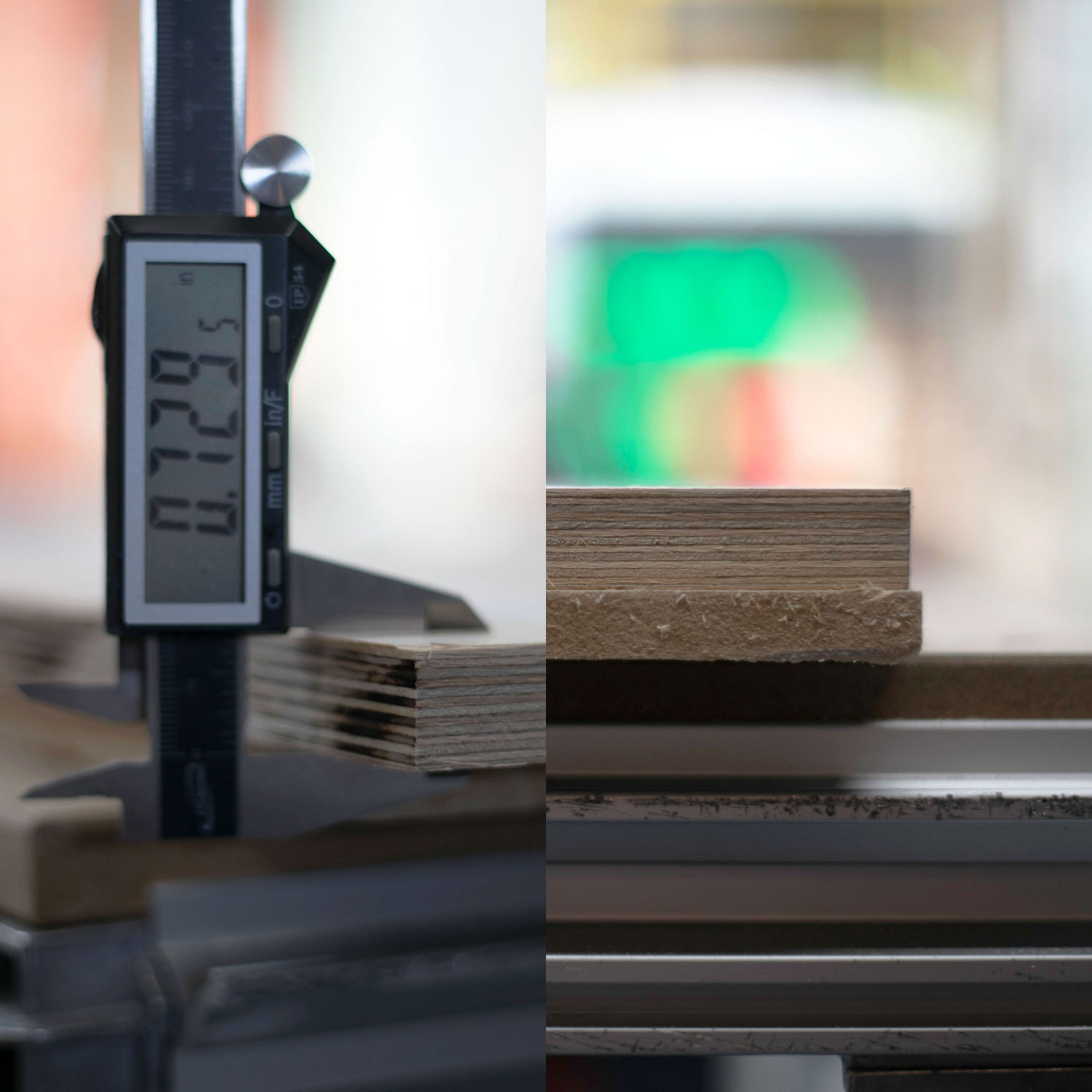
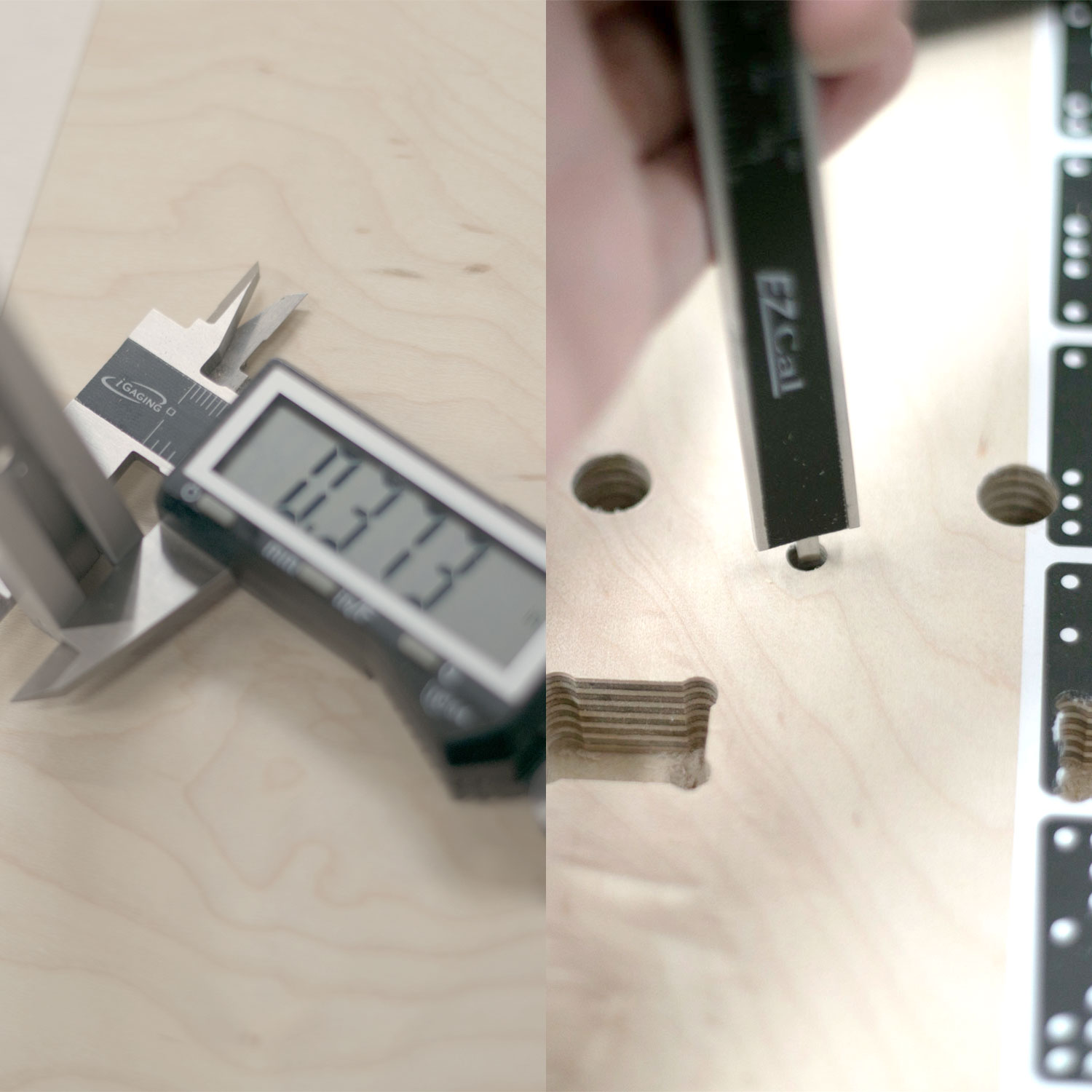
This project requires a minimum of 23in x 48in of high quality ¾” thick plywood. We strongly recommend BB-BB Baltic Birch or C2 Maple. Flatness is very important to the outcome of the project, so don’t use plywood that shows any sign of warp. The project is designed for an actual thickness of .73in with a clearance of .005in added to all interfaces. Depending on the actual thickness of your plywood and the diameter of your rod or dowel, you may need to use the offset functionality in Origin’s cut parameters to adjust fit. You will be reminded to check for fit throughout these instructions.

Prepare your work surface
Place a spoilboard measuring at least 23in x 48in on top of your work surface.
We recommend using ½” thick MDF. This is used so you can cut through your material without cutting up your work table. You can re-use this for future projects.
Apply four strips of 2in wide double sided tape to the back side of your plywood. Tape should be laid along the length of the plywood, spaced evenly at 3in and 6in from either edge (see image).
This spacing will ensure every part has adequate hold down. Peel the backing from the double-sided tape and stick the plywood to your spoil board. To ensure good adhesion, press firmly along each strip of of tape.
You can’t press too hard here, you want to make sure that your parts stay well attached to the spoil board for your finishing passes.
Clamp the plywood and spoilboard securely to the worksurface.
Some of the parts on this project may be hard to reach.

Setup Shaper Origin
Apply ShaperTape to the work surface. Tape should be applied along the width of the board, spaced every 3in - 4in.
Plug in Origin and start a New Scan
Place design in your workspace
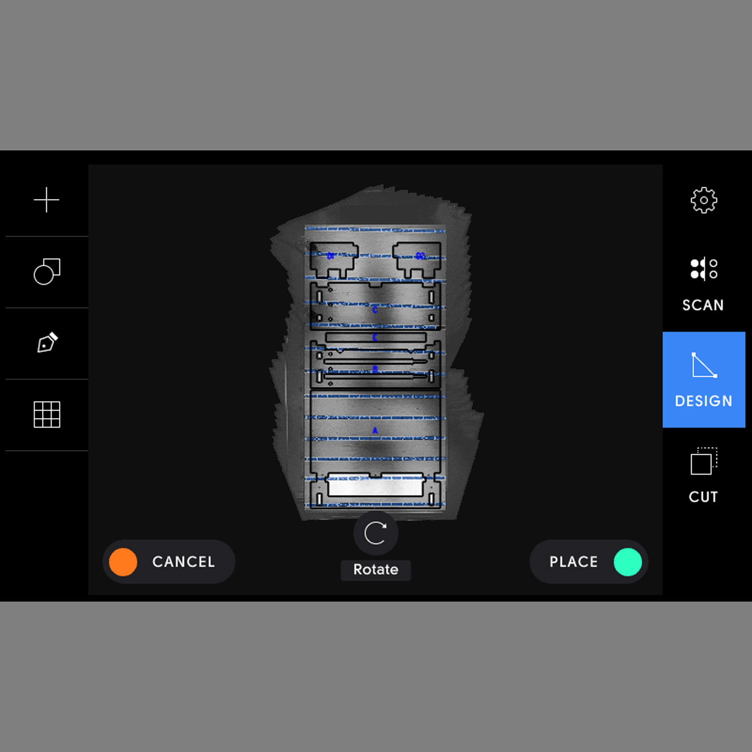
In Design mode, tap the “+” button in the top left corner of your screen to open the file browser. Select the vertical workstation and align the file roughly in the middle of your plywood, allowing for a small buffer all around the edges.
Once placed, test your placement on the workpiece. Move Origin over the extremities of your design to make sure you will be able to complete all cuts without encountering any obstacles (running into clamps, edges, or losing the view of the ShaperTape).
Install ¼” Up-Cut Bit
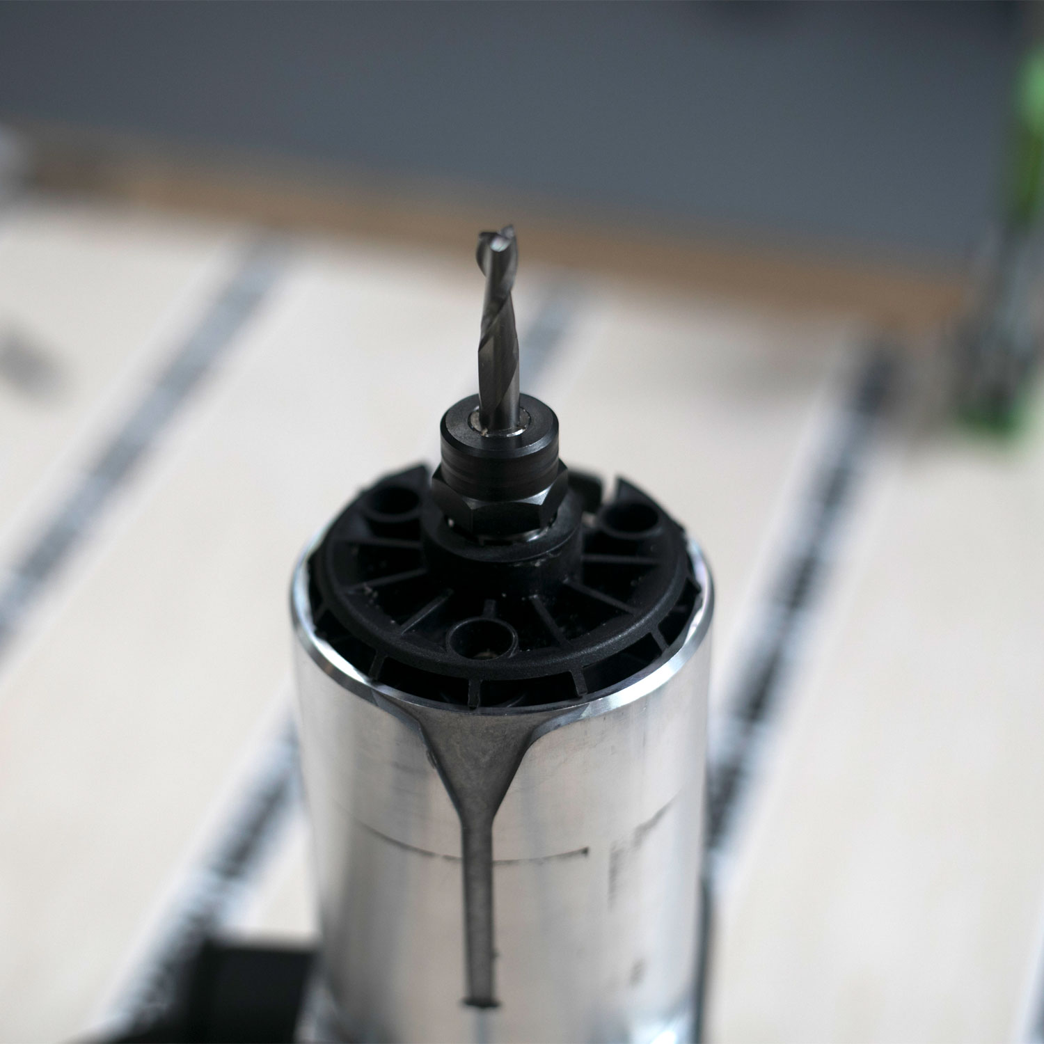
Unplug and remove the spindle from Origin and install the ¼” Up-Cut Bit into the collet making sure to adequately tighten. Re-install the spindle into the tool, tighten collar screw, and plug the spindle in.
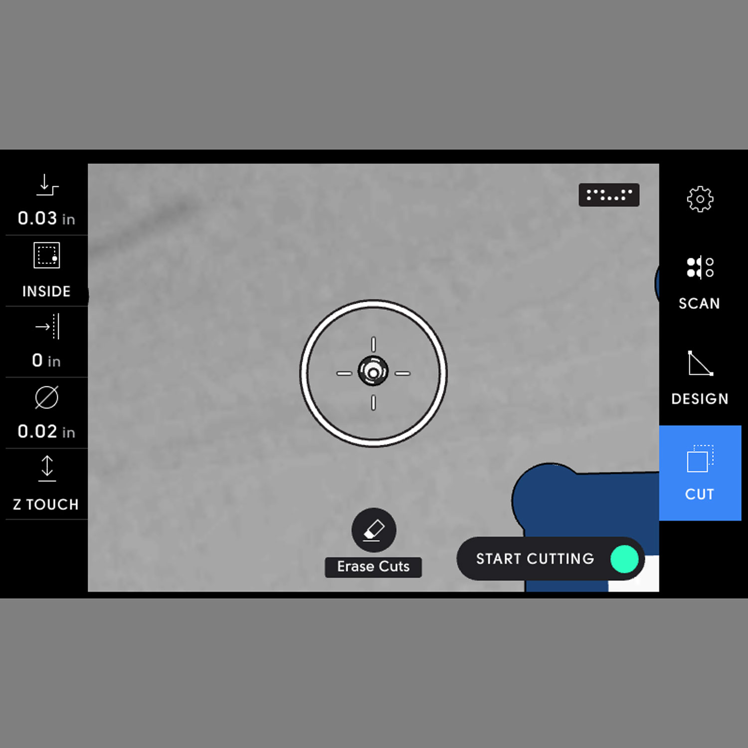
On screen (cut mode), update the following:
Bit size: ¼” (.25in)
Remember to Z-touch after changing bits

Setup to cut interior profiles (inside cut) [Parts A, B, C]
You are almost ready to cut! Before you start cutting, it is important to go over a few things. Go through steps 6 - 9 before you begin.
You will be using two different setups: one for a rough pass (roughing), and one for a final finish pass (finishing). In the rough pass, there are three separate passes required to cut through the material. This means you will be making four total passes around each profile.
Roughing:
Depth Steps:1st pass: ¼” (.25in)2nd pass: ½” (.50in)3rd pass: ¾” (.75in) [adjust this to your plywood thickness + .02” for breakthrough]Cut type: InsideOffset: 1/32 (.03in)Bit size: ¼” (.25in)Spindle speed (off screen): 5
Finishing:
Depth: ¾” (adjust this to your plywood thickness + .02” for breakthrough; i.e. if your plywood thickness measures 0.74”, you would set your depth to 0.76”)Cut type: InsideOffset: 0 (adjust in small increments to fit actual thicknesses and diameters. See step 7 for details)Bit size: ¼” (.25in)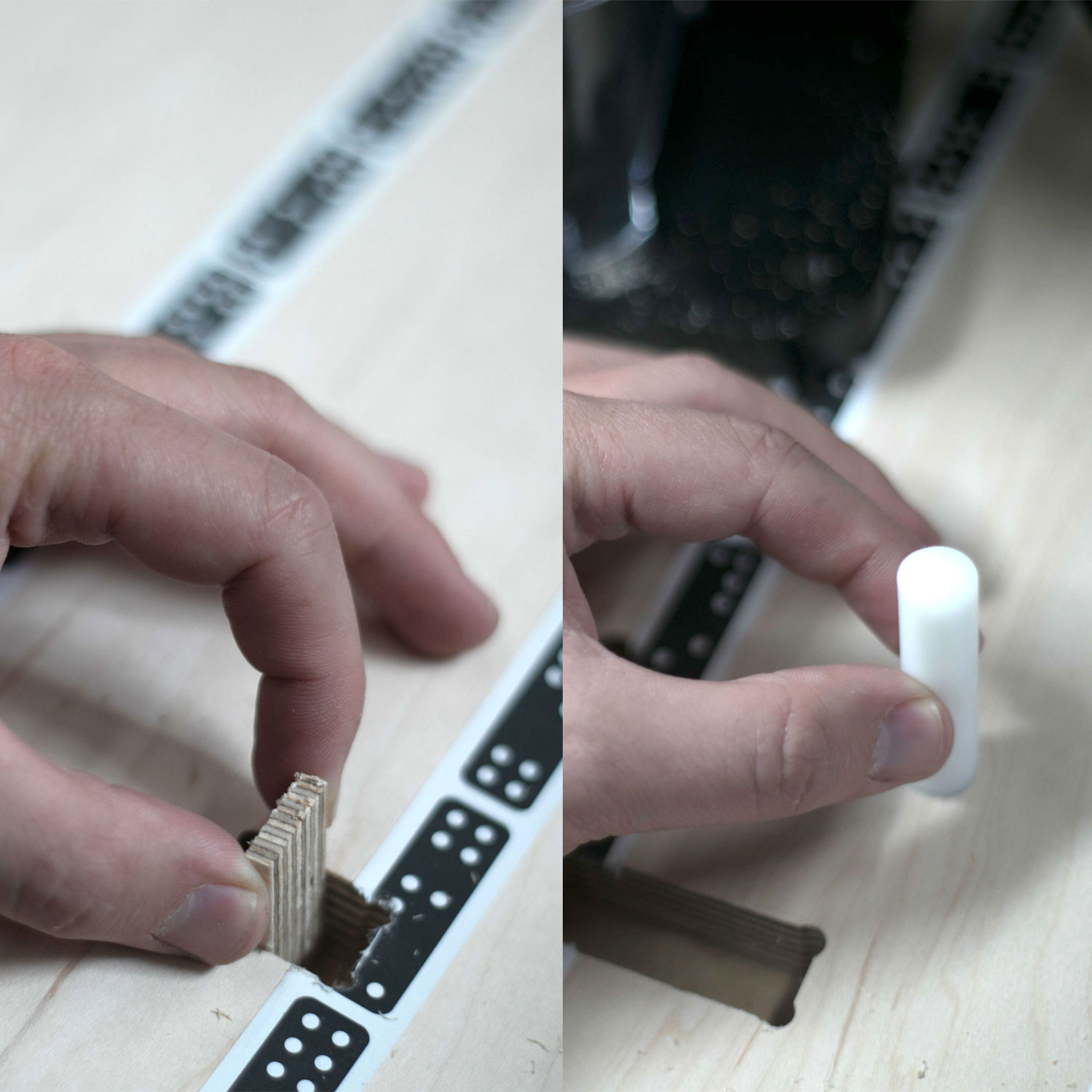
Offsets and Fitting
Note on offsets (applies only to interior profiles):
This project requires a snug fit on all parts. It is critical to take extra care when doing the final pass on the interior features. It is recommended that you start small and work your way up to a good fit. For the first of the rectangular cutouts, take a piece of the project plywood (you can use the waste material from the first cutout) and use its thickness to check your finish pass offset. Adjust your offset in small increments (.001” - .002”) until the scrap fits, but is very snug. The same applies for the alignment pins, have the rod or dowel on hand to adjust the real world fit.

Avoiding danger with small debris
Note on dangerous situations with small debris:
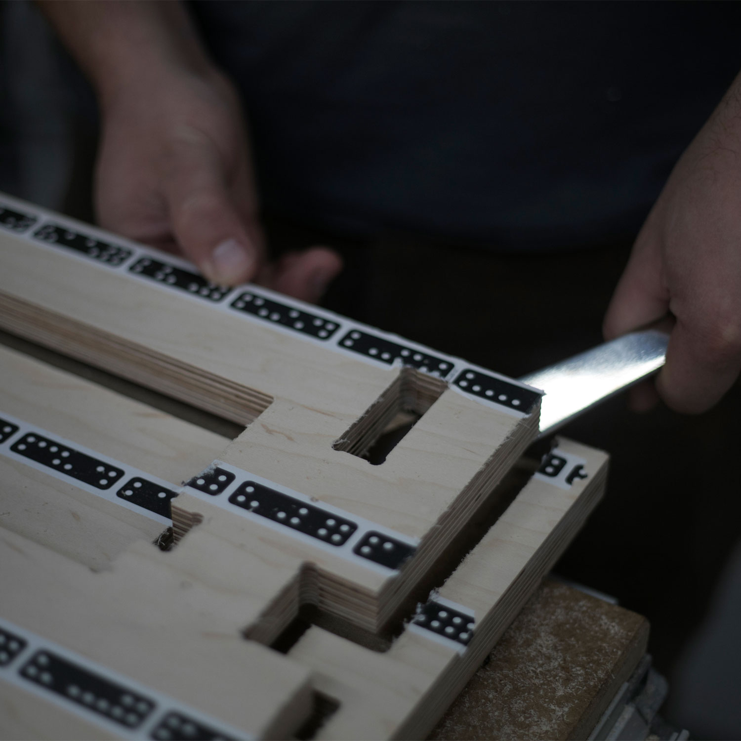
The material in the center of the small rectangular cut outs can cause a grab when it breaks away. It is best to avoid this situation all together. On your last roughing pass for each of those profiles, stop just short cutting all the way around leaving a small tab connecting the offcut to your part. Before performing the finishing pass, break out and discard that piece (use a flathead screwdriver or the handle of your 19mm wrench as a lever).

Cut interior profiles
Before cutting, always make sure you are wearing the appropriate safety equipment (eye, hearing, and respiratory).
Cut out each interior profile using the settings below (same as what was used in Step 6).
Roughing:
Depth Steps:
1st pass: ¼” (.25in)2nd pass: ½” (.50in)3rd pass: ¾” (.75in) [adjust this to your plywood thickness + .02” for breakthrough]Cut type: InsideOffset: 1/32 (.03in)Bit size: ¼” (.25in)Spindle speed (off screen): 5
Finishing:
Depth: ¾” (adjust this to your plywood thickness + .02” for breakthrough; i.e. if your plywood thickness measures 0.74”, you would set your depth to 0.76”)Cut type: InsideOffset: 0 (adjust in small increments to fit actual thicknesses and diameters. See step 7 for details)Bit size: ¼” (.25in)
Cut Track Pockets [Part B]
The pocket profiles are sized to accommodate ¾” x 15in track, but the depth will need to be set to the track thickness. Using your calipers, measure the exact thickness of your track. This depth is important, so it is good practice to verify that Origin’s depth setting is correct, and make small adjustments as needed. Use the end of your calipers to measure the depth of cut in a small area before cutting the whole pocket. If the depth is not correct, make adjustments to the depth setting before you proceed.
First, rough out the middle areas of the pockets using the below settings:
Pocketing:
Depth Steps:
1st pass: ¼” (.25in)2nd pass: .38” (adjust as needed)
Cut type: PocketOffset: 0Bit size: ¼” (.25in)Spindle speed (off screen): 5
Next, hover over the pocket profiles and switch both of them to inside cut (in the left hand menu). Cut around the inside profiles of the pockets using the settings below:
Inside Cut:
Depth: .38” (adjust as needed)Cut type: InsideOffset: 0 Bit size: ¼” (.25in)Spindle speed (off screen): 5

Cut All Exterior Profiles (outside cut) [ALL PARTS]
Use the below settings to cut out all of the exterior profiles. It will take four passes total:
Roughing:
Depth Steps:
1st pass: ¼” (.25in)2nd pass: ½” (.50in)3rd pass: ¾” (.75in) [adjust this to your plywood thickness + .02” for breakthrough]
Cut type: OutsideOffset: 1/32 (.03in)Bit size: ¼” (.25in)Spindle speed (off screen): 5
Note: After the last roughing pass on each part be sure to check that all the parts are well adhered to the spoil board. Can’t hurt to press down on the part to make sure.
Finishing:
Depth: ¾” (.75in) [adjust this to your plywood thickness + .02” for breakthrough]Cut type: OutsideOffset: 0Bit size: ¼” (.25in)Spindle speed (off screen): 5
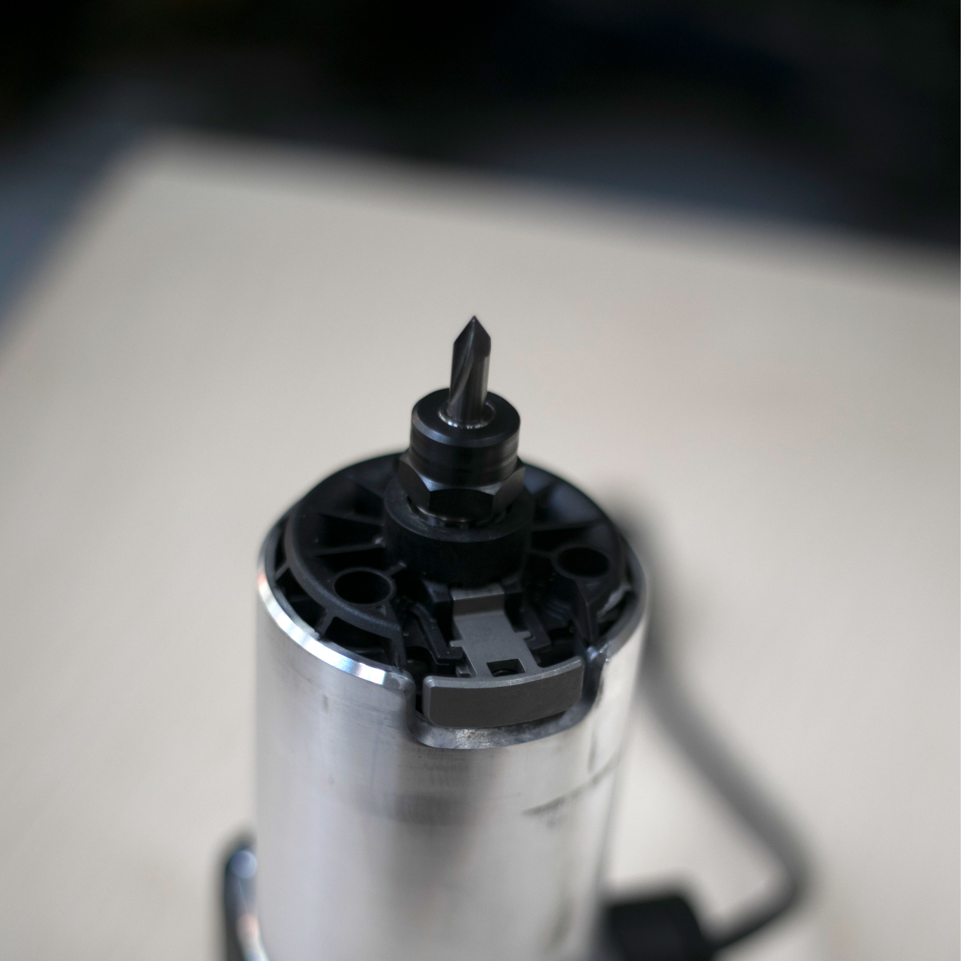
Swap to a V60 Engraving Bit (optional)
Unplug and remove the spindle from Origin and install the V60 Engraving bit into the collet making sure to adequately tighten. Re-install the spindle into the tool, tighten collar screw, and plug spindle in.
On screen (cut mode), update the following:
Bit size: V60 (.03in)Remember to Z-touch after changing the bit
Mark screw holes for drilling
Using screws to fasten the fixture together is optional. We have found it to be helpful in the assembly of the workstation, as it pulls all the parts together. Glue and clamps will also work, if that is the fastening method you prefer.
If following this step, adjust your cut settings to match the settings below:
Depth: .03”Cut type: InsideOffset: 0 Bit size: V60 (.03in) Spindle speed (off screen): 2
Find the five small circles on the lower half of Part A, and use the engraving bit to mark each of them. These will serve as center marks for your pilot drill.
Pry up and clean parts
Pry up all the parts from your spoilboard, remove the double sided tape and ShaperTape from the parts, and use sandpaper to smooth any rough/fuzzy edges.
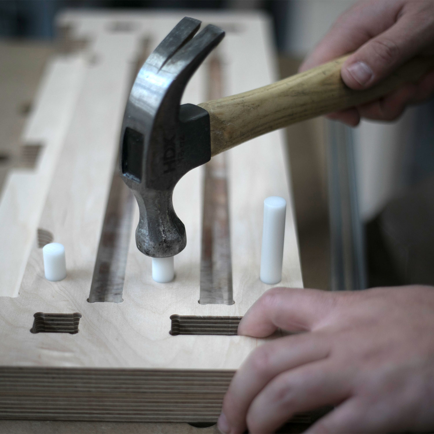
Begin assembly and install Delrin Rod
If you haven’t already done so, cut your T-Track and Rod/Dowel to length.
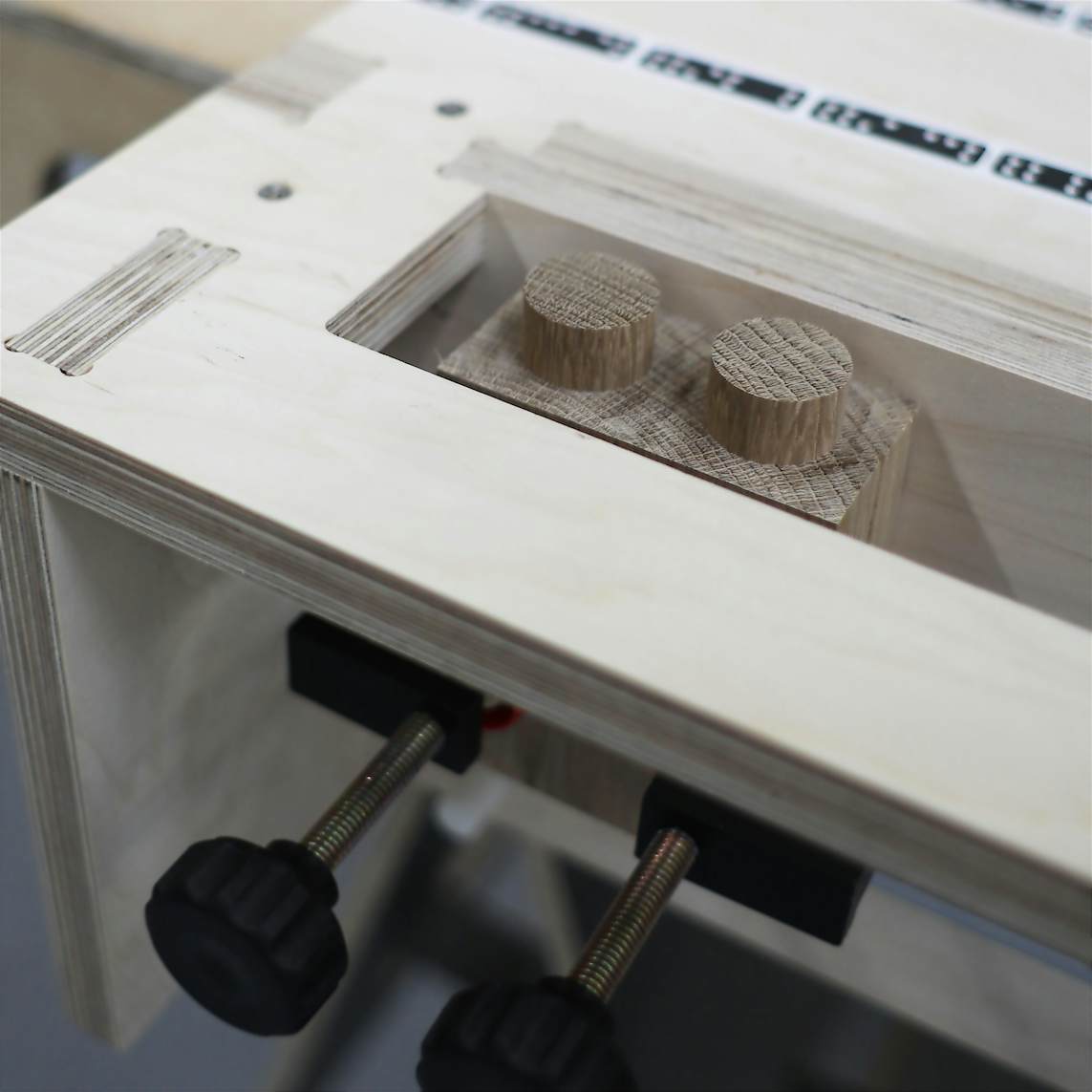
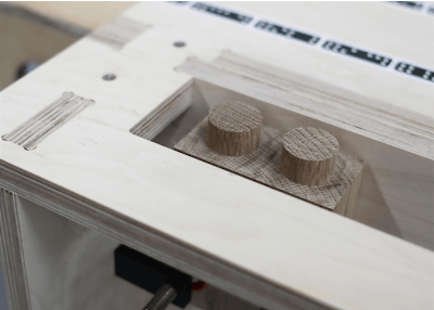
Begin assembly by laying Part B on top of Part C. Using a claw hammer, pound the three pieces of rod/dowel into each of the three corresponding holes.
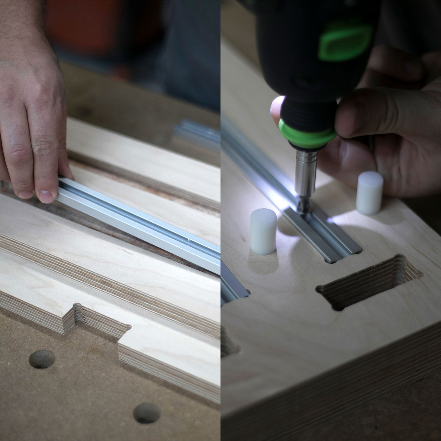
Fit and fasten T - Track
Fit the two pieces of T-Track into their slots, and fasten with #6 x 1” screws (screws will go through the back of Part B into Part C).

Complete lower assembly
Next, insert parts D1 and D2 into the front (t-track side) of Part B and pound in with a rubber mallet.

Fit lower assembly into Part A
Turn Part A upside down, and fit the Lower assembly into the corresponding holes. Pound in with a rubber mallet.
It may be easier to do this on a hard surface with your spoilboard placed under Part A.

Drill pilot holes in Part A (optional)
Using a #8 Pilot drill, drill and countersink on each of the five center marks made with the engraving bit on in Step 13.
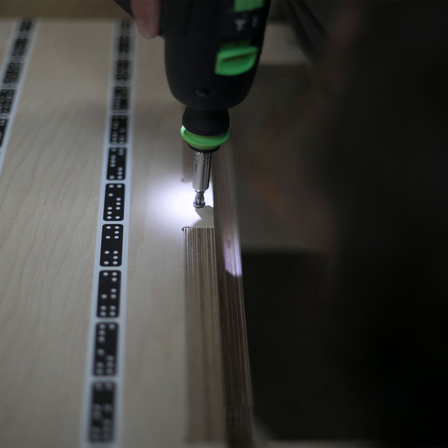
Fasten Part A to the Lower Assembly (optional)
Drive #8 x 1.5” screws into each of the pilot holes to pull the lower assembly into Part A.
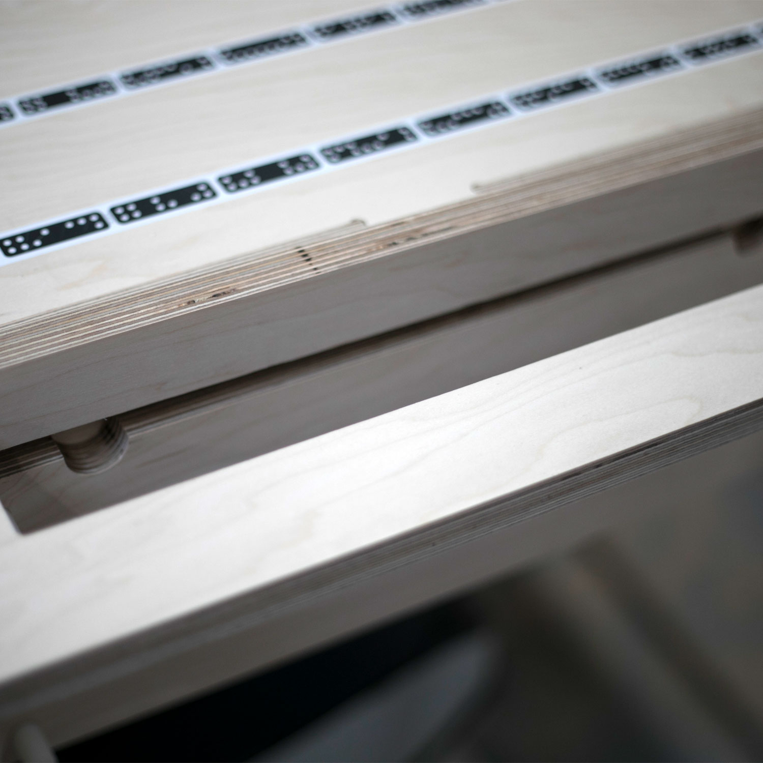
Fit Spoilboard
Install spoilboard (Part E) by inserting it through the top of Part A into the Lower Assembly. The spoilboard is removable so that it can be replaced when necessary. Note that there are four good sides to each spoilboard; be sure to rotate through each before installing a new one.
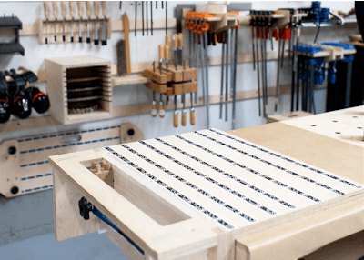
Put your new workstation to use!
Next check out how to create Mortise and Tenon joinery with Origin.
Check out the tutorials to learn more about how to get the most out of Origin!